← Home · Geophysics

Electrical Resistivity / VES (Vertical Electrical Sounding) in Columbus Georgia: Subsurface Stratigraphy Without Excavation

Together, we solve the challenges of tomorrow.

DETAILS →

The geotechnical contrast between the stable clay residuum north of Macon Road and the alluvial deposits close to the Chattahoochee River is something every local contractor learns quickly. In the northern commercial corridors, weathered mica schist lies within 15 feet of the surface, while downtown Columbus and the Bibb City area sit on up to 40 feet of variable sand and silt overlying partially decomposed rock. This lateral heterogeneity influences everything from excavation support to shallow foundation bearing pressures. Electrical resistivity methods, specifically Vertical Electrical Sounding (VES), let us map these transitions before a single bucket is moved. By injecting current and measuring potential difference at expanding electrode spacings, we reconstruct a 1D resistivity profile that correlates directly with grain size, moisture content, and rock quality. The technique works well in the humid subtropical climate of Columbus Georgia, where the upper Piedmont saprolite retains enough ionic conductivity to generate clean, interpretable curves.

Resistivity contrasts in the Piedmont saprolite can drop from 200 Ω·m to under 30 Ω·m across the groundwater interface, giving us a clear target horizon for dewatering and excavation planning.

Process overview

Columbus Georgia grew as a mill town on the fall line, and the early industrial development left a patchwork of fill, buried foundations, and modified drainage that complicates modern site investigation. Standard borings tell you what is at the drill point, but resistivity sounding fills the gaps between them. The Schlumberger array we deploy uses a maximum current electrode half-spacing of 100 meters, providing investigation depths down to roughly 50 meters in the typical silty sands of the Columbus area. Data interpretation follows the resistivity forward modeling routines described in ASTM D6431, with iterative curve matching to constrain layer thickness and true resistivity. When we cross-check the inverted resistivity model against a Standard Penetration Test boring, the correlation between resistivity and N60 blow count can be calibrated site-wide, extending the value of the point data across the entire parcel. This matters for projects along Veterans Parkway, where the transition from Piedmont crystalline rock to Coastal Plain sediments can occur over less than 200 horizontal feet, creating differential settlement risks that only a continuous geophysical profile can reveal.
Electrical Resistivity / VES (Vertical Electrical Sounding) in Columbus Georgia: Subsurface Stratigraphy Without Excavation
Technical reference image — Columbus Georgia

Local context

One pattern we observe repeatedly in Columbus Georgia is the misinterpretation of low-resistivity zones in the upper 3 meters as groundwater when they are actually saturated clay-rich fill from mid-20th-century construction. Running a VES survey without local calibration against a test pit or auger boring can lead to overestimating the depth to competent bearing strata. The real risk shows up when resistivity values between 10 and 25 Ω·m are automatically equated to water without considering the cation exchange capacity of the local kaolinitic clays derived from weathered schist. We have seen projects on the east side near Fort Benning where geophysical-only reports misidentified a perched water lens as the regional water table, triggering unnecessary dewatering specifications. Our approach combines the resistivity sounding with at least one ground-truth point, and we interpret the resistivity curve using formations known from the USGS Columbus geologic quadrangle, so that a 20 Ω·m layer in the saprolite is correctly attributed to saturated fines rather than clean sand.

Need a geotechnical assessment?

Reply within 24h.

Email: contact@geotechnicalengineering1.sbs

Technical parameters

ParameterTypical value
Array configurationSchlumberger (standard), Wenner optional for lateral profiling
Maximum investigation depth50 m below grade (AB/2 ≤ 100 m)
Typical electrode spacing rangeAB/2 from 1.5 m to 100 m, MN/2 adaptive
Measurement resolutionLayer thickness ≥ 15% of depth to layer top
Data processingIPI2Win or RES1D inversion, RMS error < 5%
Reporting standardASTM D6431-18 for surface resistivity, cross-plots with N60 where available
Typical survey duration45-90 minutes per VES point, depending on access and line layout
Output deliverablesResistivity-depth curve, interpreted lithologic log, iso-resistivity cross-sections

Additional services

01

VES Depth Profiling for Foundation Design

One-dimensional resistivity soundings spaced on a 50- to 100-foot grid to map depth to bedrock and identify soft zones. We deliver interpreted cross-sections showing the resistivity stratigraphy, correlated with any available boring logs, to guide footing elevation decisions and reduce the number of borings required.

02

Groundwater and Perched Water Mapping

Resistivity contrasts across the phreatic surface are pronounced in the sands and silty sands of the Chattahoochee floodplain. We run VES transects perpendicular to the river to delineate the saturated zone and detect perched intervals above clay lenses, information that directly feeds dewatering system design and cut-slope stability calculations.

03

Fill and Anomaly Detection

Urban parcels in Columbus often contain buried demolition debris, old utility corridors, or undocumented fill that standard borings can miss. We run close-spaced resistivity lines to flag anomalies below 10 Ω·m (possible metallic objects or contaminated soil) and above 500 Ω·m (voids or dry granular fill), mapping their extent before intrusive investigation targets them precisely.

Reference standards

ASTM D6431-18 Standard Guide for Using the Direct Current Resistivity Method for Subsurface Investigation, ASTM D5777-18 Standard Guide for Using the Seismic Refraction Method for Subsurface Investigation (cross-reference for velocity-resistivity correlation), NCHRP Synthesis 357: Use of Geophysics for Transportation Projects

FAQ

How deep can a VES survey investigate in the Columbus Georgia area?

With a maximum current electrode half-spacing of 100 meters, we reliably resolve layers to approximately 50 meters below ground surface in the silty sands and saprolite common to the Columbus area. The actual depth of investigation depends on the resistivity contrast between layers: a high-resistivity bedrock beneath conductive clay will be detected at shallower depths than a gradational contact. We adjust the maximum AB/2 spacing on site based on the apparent resistivity curve as it develops, extending the line if deeper penetration is needed.

What does a VES survey cost for a typical residential or commercial lot in Columbus?

For a standard VES survey in the Columbus Georgia area, the cost ranges from US$570 to US$950 per sounding, depending on the maximum electrode spread required and the number of soundings on the site. A typical house lot investigation with 3 VES points and a brief interpretative report falls toward the lower end of that range, while a commercial site requiring longer lines, multiple soundings, and correlation with existing boring data will be at the upper end.

Can electrical resistivity distinguish between clay and clean sand in the Piedmont saprolite?

Yes, and this is one of the most useful applications in our region. The kaolinitic clays derived from weathered mica schist typically show resistivity values between 8 and 25 Ω·m when saturated, while clean alluvial sands of the Chattahoochee River read between 60 and 200 Ω·m depending on grain size and saturation. The intermediate silty sands common to the transition zone fall in the 30-60 Ω·m range. We calibrate these ranges against at least one boring or test pit on every project to account for local pore-water chemistry.

How long does a VES survey take, and what site access is required?

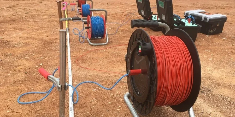
A single VES sounding takes between 45 and 90 minutes to complete, including electrode layout, measurement, and preliminary curve plotting. We need a clear straight-line path of up to 200 meters for the full electrode spread, though shorter lines can be used for shallower targets. The electrodes are small steel stakes driven a few inches into the ground, so we can work on grass, asphalt (with conductive gel), or compacted soil. We do need to avoid buried metallic utilities parallel to the spread because they distort the current field.

How do you validate the resistivity interpretation against actual soil conditions?

We never rely on resistivity data in isolation. On every project in Columbus Georgia, we correlate the VES curves with at least one direct observation point: an SPT boring, a test pit, or an existing geotechnical log from a nearby parcel. The resistivity layering is then tied to known formations from the USGS geologic map, and we run inversion models that honor the measured thickness of any logged strata. This ground-truthing step is what separates a reliable resistivity report from a speculative one.

Location and service area

We serve projects across Columbus Georgia and its metropolitan area.

View larger map